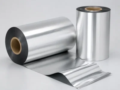
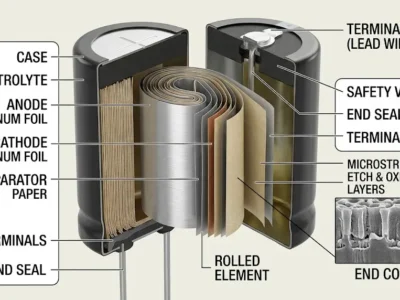
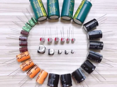
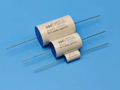
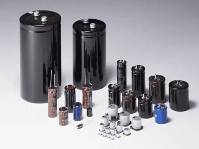
Capacitor foil sits at the heart of modern electronics. It is the thin metal layer that stores and releases electrical energy inside capacitors.
Without it, smartphones, electric vehicles, and power grids would not work the way they do today.
What Is Capacitor Foil?
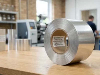
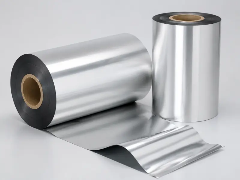
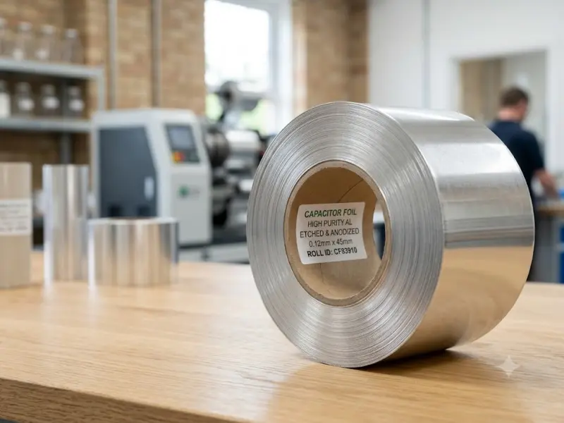
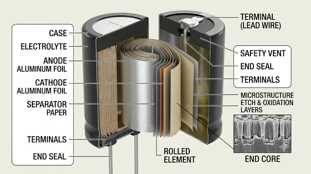
Capacitor foil is a specialized aluminum strip. Manufacturers roll it down to micrometer thickness, then clean it, etch it, or form it into anodes and cathodes. The goal is simple: create a huge surface area in a tiny space. More surface area means more energy storage.
Most capacitor foil starts as high-purity aluminum. Purity levels reach 99.99% in some grades. That purity matters because even tiny impurities can cause current leakage or early failure.
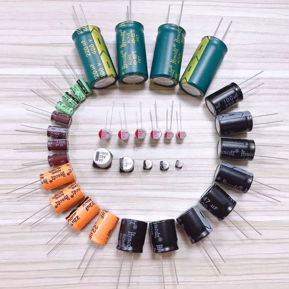
The foil goes into electrolytic capacitors, film capacitors, and supercapacitors. Each type demands a different foil thickness, alloy, and surface treatment.
Why Aluminum Leads the Market
Aluminum dominates the capacitor foil world. It is light, cheap, and forms a stable oxide layer. That oxide layer acts as the dielectric in electrolytic capacitors. No other metal offers the same balance of cost and performance.
Copper and tantalum exist as alternatives, but they cost more. Aluminum capacitor foil remains the go-to choice for consumer electronics, automotive systems, and industrial power supplies.
Common Capacitor Foil Types
Plain Capacitor Foil
→ Used as the basic aluminum electrode material for capacitor production.
Etched Capacitor Foil
→ Processed with surface etching to increase effective surface area and improve capacitance performance.
Forming Capacitor Foil
→ Electrochemically treated foil that creates an oxide dielectric layer for capacitor operation.
High Voltage Capacitor Foil
→ Designed for applications requiring higher voltage resistance and stable electrical performance.
Low Voltage Capacitor Foil
→ Suitable for general electronic devices and compact capacitor products.
Main Applications
- Aluminum electrolytic capacitors
- Power supply capacitors
- Industrial electronic equipment
- Energy storage systems
- Automotive electronics
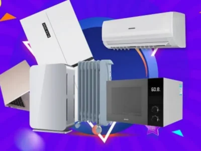
- Consumer electronics
- LED lighting systems
- Inverter and converter equipment
- Renewable energy equipment
- Electrical control systems
Product Advantages
→ High electrical conductivity
→ Excellent electrochemical performance
→ Stable capacitor operation
→ Low thickness variation
→ Good winding performance
→ Suitable for high-speed capacitor production
→ Reliable performance in long-term operation
→ Supports customized specifications for different capacitor designs
Typical Capacitor Foil Production Process
Aluminum Casting
↓
Hot Rolling
↓
Cold Rolling
↓
Annealing Treatment
↓
Slitting
↓
Surface Inspection
↓
Capacitor Manufacturing
The precise production process ensures consistent thickness, excellent surface quality and stable electrical performance for capacitor applications.
Capacitor Foil Types by Function
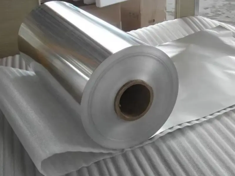
Not all foil plays the same role inside a capacitor. Some foils store charge. Others simply conduct current. Here is how they split.
Anode Foil
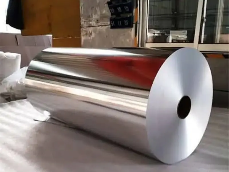
Anode foil carries the positive charge. Manufacturers etch it to create millions of microscopic tunnels. Then they form an aluminum oxide layer on the surface. This oxide is the dielectric. Thicker oxide means higher voltage rating.
Typical thickness: 0.03 mm to 0.12 mm
Typical purity: 99.98% or higher
Common alloys: 1050, 1070, 1100
Cathode Foil
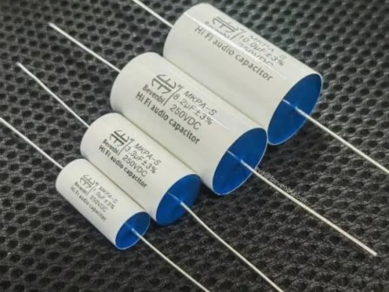
Cathode foil sits on the negative side. It does not need the same oxide layer. Its job is to contact the electrolyte and complete the circuit. Cathode foil is usually thinner and less pure than anode foil.
Typical thickness: 0.02 mm to 0.05 mm
Typical purity: 99.80% to 99.95%
Common alloys: 1070, 3003, 8011
Etched Foil
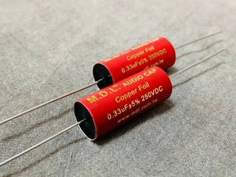
Etched foil goes through an electrochemical process. Acid baths eat tiny holes into the surface. This multiplies the effective area by 50 to 100 times. Etched foil is what lets a small capacitor hold thousands of microfarads.
Formed Foil
Formed foil is etched foil that has already received its oxide layer. Some capacitor makers buy formed foil ready to wind. Others buy plain etched foil and do the forming themselves.
Alloy Breakdown: Which Metal Fits Your Design?
Alloy choice changes everything. It affects conductivity, corrosion resistance, and how well the foil etches. Here is a clear comparison.
| Alloy | Purity | Key Traits | Best For |
|---|---|---|---|
| 1050 | 99.50% | High conductivity, soft, easy to form | Low-voltage cathodes, general purpose |
| 1070 | 99.70% | Better purity than 1050, excellent etching | Mid-voltage anodes, consumer electronics |
| 1100 | 99.00% | Good strength, slightly lower purity | Structural parts, less critical layers |
| 3003 | 97.00% | Manganese added, stronger, less pure | Cathode foil where mechanical strength matters |
| 8011 | 98.00% | Iron and silicon added, good formability | Specialty capacitors, foil-winding applications |
High-purity alloys like 1070 and 1080 dominate anode production. Cathode foil can tolerate lower purity because it does not hold the dielectric layer.
Temper and State: H18 vs O Condition
After rolling, aluminum foil gets a temper designation. This tells you how hard or soft the metal is. Capacitor makers care because hard foil cracks during winding. Soft foil deforms too easily.
H18 Temper (Full Hard)
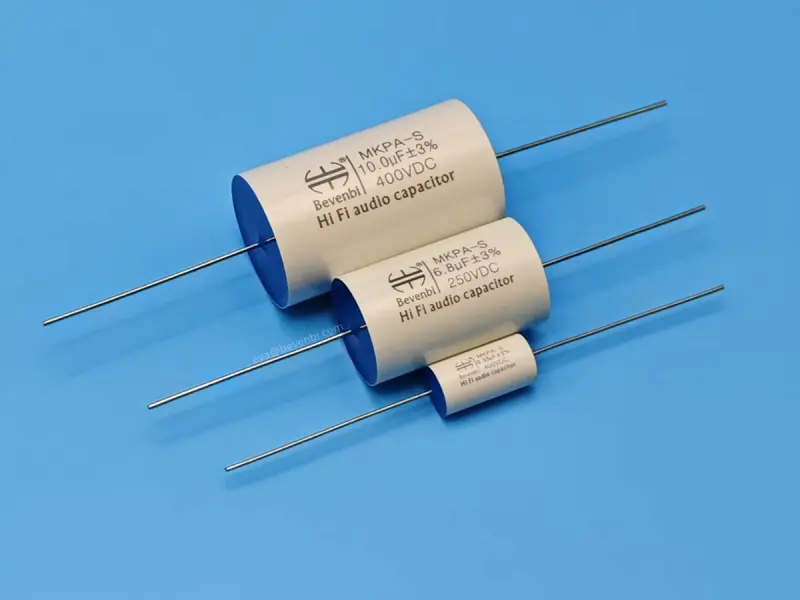
H18 foil is work-hardened. It holds its shape well. That makes it good for applications where the foil must stay flat during assembly. However, it is less flexible.
Typical use: Formed foil that ships flat
Thickness range: 0.04 mm to 0.10 mm
O Temper (Soft Annealed)
O temper foil is fully annealed. It bends easily without cracking. Winding machines love O temper because it wraps smoothly around a core. Most cathode foil uses O temper.
Typical use: Wound cathode layers, flexible assemblies
Thickness range: 0.02 mm to 0.06 mm
H16 and H14 (Intermediate)
Some makers use H16 or H14 as a middle ground. These offer more strength than O temper but more flexibility than H18. They work well in mid-voltage capacitors where the foil must hold shape during heat treatment but still wind cleanly.
Thickness Guide: Micrometers Matter
Thickness directly impacts capacitance, voltage, and physical size. Thinner foil packs more layers into the same can. Thicker foil handles higher voltage. Here is how the ranges map to real products.
| Thickness Range | Typical Use | Voltage Class | Capacitor Type |
|---|---|---|---|
| 0.02 – 0.03 mm | Cathode layers, low-voltage | 6.3V – 16V | SMD electrolytic |
| 0.03 – 0.05 mm | Standard anode, consumer grade | 16V – 50V | Radial electrolytic |
| 0.05 – 0.08 mm | Power supply anodes | 100V – 250V | Snap-in, screw terminal |
| 0.08 – 0.12 mm | High-voltage formed foil | 350V – 550V | Large can, inverter grade |
| 0.12 – 0.15 mm | Extra-high voltage, motor run | 600V+ | Motor start, industrial |
Some specialty foils go below 0.02 mm for miniature capacitors. Others exceed 0.15 mm for heavy-duty industrial units.
Surface Treatment: Etched vs Plain
The surface finish separates basic foil from high-performance foil.
Plain Foil
Plain foil has a smooth or lightly textured surface. It costs less. It works in simple capacitors where space is not tight and capacitance demands are low.
DC Etched Foil
Direct current etching creates fine, straight tunnels. These run deep into the metal. DC etched foil delivers high capacitance per unit area. It is the standard for most aluminum electrolytic capacitors.
AC Etched Foil
Alternating current etching creates a spongy, irregular surface. The pores are shorter but more numerous. AC etched foil suits low-voltage capacitors where surface area matters more than tunnel depth.
Formed Oxide Layer
The oxide layer thickness depends on the forming voltage. A 400V forming process creates a thicker oxide than a 16V process. Here is a rough mapping.
| Forming Voltage | Oxide Thickness (approx.) | Application |
|---|---|---|
| 16V – 25V | 0.02 – 0.03 μm | Consumer electronics |
| 50V – 100V | 0.08 – 0.15 μm | Power adapters |
| 200V – 250V | 0.30 – 0.40 μm | LED drivers |
| 400V – 500V | 0.60 – 0.80 μm | PFC circuits, inverters |
Where Capacitor Foil Shows Up
Capacitor foil hides inside devices people use every day. Here is a quick look at the main markets.
- Smartphones and tablets — Tiny SMD capacitors smooth power to the processor. Foil thickness here can be under 0.03 mm.
- Laptops and desktops — Motherboards hold hundreds of electrolytic and solid capacitors. Each one contains etched or formed foil.
- LED lighting drivers — High-voltage capacitors need thick formed foil, often 0.08 mm or more.
- Electric vehicle inverters — EV powertrains demand capacitors that survive heat and vibration. Heavy-gauge foil, 0.10 mm and up, handles the load.
- Solar inverters — DC-link capacitors in solar systems use large-can electrolytics with high-purity anode foil.
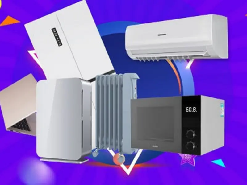
- Air conditioners and refrigerators — Motor run capacitors rely on capacitor foil for reliable startup.
- Medical devices — Defibrillators and imaging equipment need stable, low-leakage capacitors. Ultra-high-purity 1070 or 1080 foil is common.
- Aerospace and defense — Custom alloys and tight thickness tolerances meet MIL-spec requirements.
- 5G base stations — Power supply modules in telecom gear use mid-voltage foil in high quantities.
Anode Foil vs Cathode Foil: Side by Side
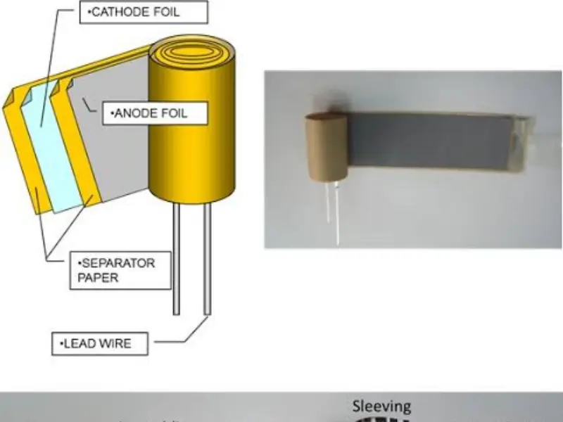
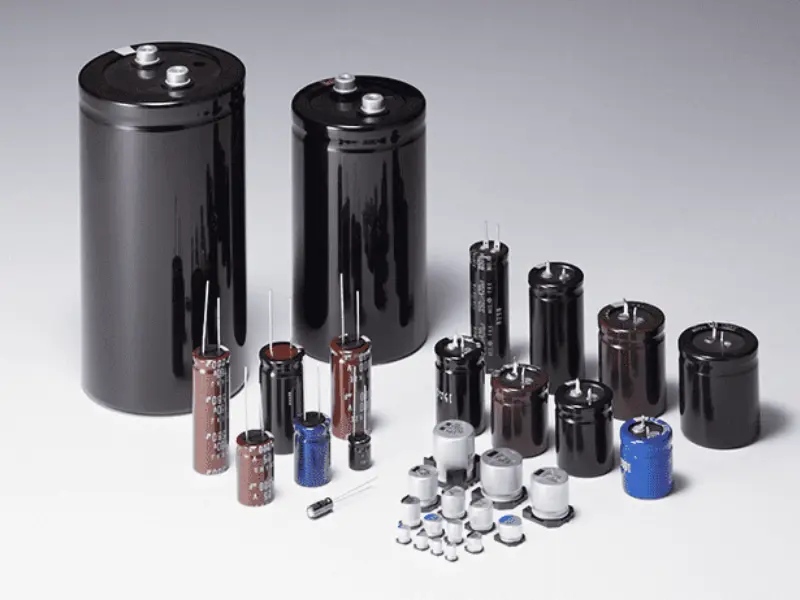
These two foils live in the same capacitor but serve completely different roles. Mixing them up causes failure.
| Feature | Anode Foil | Cathode Foil |
|---|---|---|
| Main job | Store charge via oxide layer | Conduct current to electrolyte |
| Purity needed | 99.98% – 99.99% | 99.80% – 99.95% |
| Typical alloy | 1070, 1080, 1050 | 1070, 3003, 8011 |
| Thickness range | 0.03 – 0.15 mm | 0.02 – 0.05 mm |
| Surface treatment | Etched + formed | Etched or plain |
| Oxide layer | Required, thick | Minimal or none |
| Cost | Higher | Lower |
High Voltage vs Low Voltage Foil
Voltage rating drives almost every foil decision. Here is how the two worlds differ.
Low Voltage Foil (6.3V – 50V)
Low voltage foil focuses on surface area. Etching is aggressive. The oxide layer is thin. Foil can be very thin because it does not need to block high electric fields.
Typical thickness: 0.02 mm – 0.05 mm
Etch type: AC or light DC
Alloy: 1070, 1050
High Voltage Foil (200V – 600V+)
High voltage foil needs a thick, uniform oxide. Any pinhole or thin spot causes breakdown. The foil itself is thicker to handle mechanical stress during forming.
Typical thickness: 0.06 mm – 0.15 mm
Etch type: Controlled DC
Alloy: 1080, 1070 (ultra-high purity)
Solid Capacitor Foil vs Wet Electrolytic Foil
Solid aluminum capacitors use a conductive polymer instead of liquid electrolyte. The foil inside still matters.
| Aspect | Wet Electrolytic | Solid Polymer |
|---|---|---|
| Foil purity | 99.98%+ | 99.99%+ |
| Etch depth | Deep tunnels for high capacitance | Moderate etch |
| Oxide quality | Standard forming | Extra uniform |
| Cathode material | Liquid electrolyte + cathode foil | Conductive polymer |
| ESR performance | Moderate | Very low |
| Foil thickness | Wider range | Usually thinner |
Solid capacitors often use thinner anode foil because the polymer contacts the surface more evenly than liquid.
ECOSYSTEM
How to Pick the Right Capacitor Foil
Choosing foil is not guesswork. Engineers look at four things.
Voltage requirement — This sets the oxide thickness and forming voltage. Higher voltage means thicker foil and deeper forming.
Capacitance target — More capacitance needs more surface area. That means heavier etching or thinner foil to fit more layers.
Physical size limit — If the capacitor can must stay small, the foil must be thin. Below 0.03 mm is common in SMD parts.
Temperature environment — Hot environments stress the oxide layer. Higher purity foil and better forming processes improve life at 105°C or 125°C.
Supply Formats: What You Actually Receive
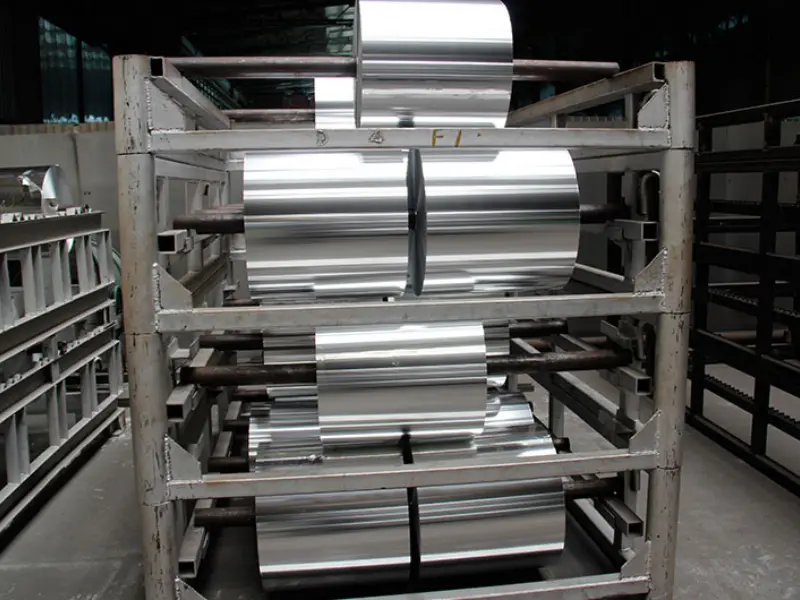
Capacitor foil ships in several formats. Pick the one that matches your winding or stacking equipment.
| Format | Width Range | Length | Best For |
|---|---|---|---|
| Jumbo roll | 500 – 1400 mm | Thousands of meters | Large capacitor factories |
| Slit roll | 20 – 500 mm | Hundreds of meters | Medium production lines |
| Ribbon | 5 – 20 mm | Custom cut | Precision wound parts |
| Pre-cut sheets | Custom | Single pieces | Lab use, prototype assembly |
Most buyers choose slit rolls. They balance handling ease with minimal waste.
Quality Checks That Matter
Not all capacitor foil is equal. Reputable suppliers run these tests.
Tensile strength — Winding machines pull foil under tension. Weak foil snaps and stops production.
Thickness uniformity — Measured across the full roll width. Variation must stay within ±2% for precision capacitors.
Purity verification — Spectrometry confirms aluminum content. Even 0.01% impurity can ruin high-voltage performance.
Etch tunnel inspection — Electron microscopy checks tunnel density and depth. Low tunnel count means low capacitance.
Oxide breakdown voltage — Samples get tested to destruction. The breakdown must exceed the rated forming voltage by a safe margin.
Global Standards and Specs
Capacitor foil follows industry norms. These specs help buyers compare suppliers.
- ASTM B373 — Standard for aluminum foil used in capacitors. Covers thickness, tensile strength, and chemical composition.
- JIS C 2300 — Japanese industrial standard for capacitor-grade aluminum foil. Common in Asian supply chains.
- IEC 60384 — Generic specification for fixed capacitors. Includes reliability tests that indirectly govern foil quality.
- RoHS / REACH — Environmental rules restrict cadmium, lead, and other impurities in the foil and its coatings.
FAQ
What is the thinnest capacitor foil available?
The thinnest production foil runs around 0.015 mm. It is used in miniature SMD electrolytic capacitors for phones and wearables. Below that, handling becomes difficult and tear rates rise.
Which alloy is best for high-voltage anodes?
Alloy 1080 or ultra-high-purity 1070 is the top choice. These grades push aluminum content above 99.98%. That purity reduces impurity-related leakage and lets the oxide layer form more uniformly at high voltages.
Can I use cathode foil as anode foil?
No. Cathode foil lacks the purity and surface preparation needed for stable oxide growth. Using it as an anode leads to high leakage current, early failure, and possible capacitor rupture.
Why does etched foil cost more than plain foil?
Etching adds steps. The foil goes through acid baths, electrochemical tunnels, rinsing, and drying. Each step requires chemicals, electricity, and tight process control. The result is 50 to 100 times more surface area, but the cost reflects that effort.
How does temper affect winding speed?
Soft O temper foil winds faster because it bends easily around small cores. Hard H18 foil resists bending and can crack at tight diameters. Most high-speed winding lines specify O temper for cathode layers.
What is the difference between DC etched and AC etched foil?
DC etched foil has long, straight tunnels running deep into the metal. It gives high capacitance gain and suits most electrolytic capacitors. AC etched foil has a sponge-like surface with many short pores. It works better for very low voltage capacitors where tunnel depth is less important than total pore count.
Does thicker foil always mean higher voltage?
Not always, but usually. Voltage rating depends mainly on oxide thickness. However, thicker foil handles the mechanical stress of deeper etching and higher forming voltages better. So high-voltage foils tend to be thicker as a practical matter.
How do I store capacitor foil before use?
Keep rolls dry and away from acids or salts. Humidity causes surface oxidation that hurts forming quality. Room temperature storage in sealed packaging is ideal. Avoid stacking heavy objects on rolls to prevent edge damage.
What surface finish should I specify for formed foil?
Formed foil should have a uniform oxide color. Patchy or cloudy areas signal uneven forming. The surface should feel smooth to the touch, not chalky. A chalky oxide layer may be too thick or poorly bonded.
Is recycled aluminum suitable for capacitor foil?
No. Recycled aluminum contains too many impurities. Capacitor foil demands primary aluminum refined to 99.95% or higher. Even trace iron or copper ruins dielectric performance.